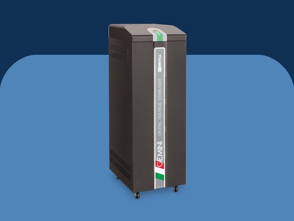
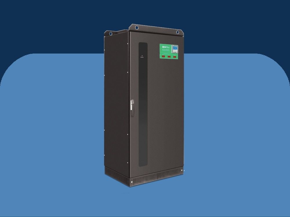
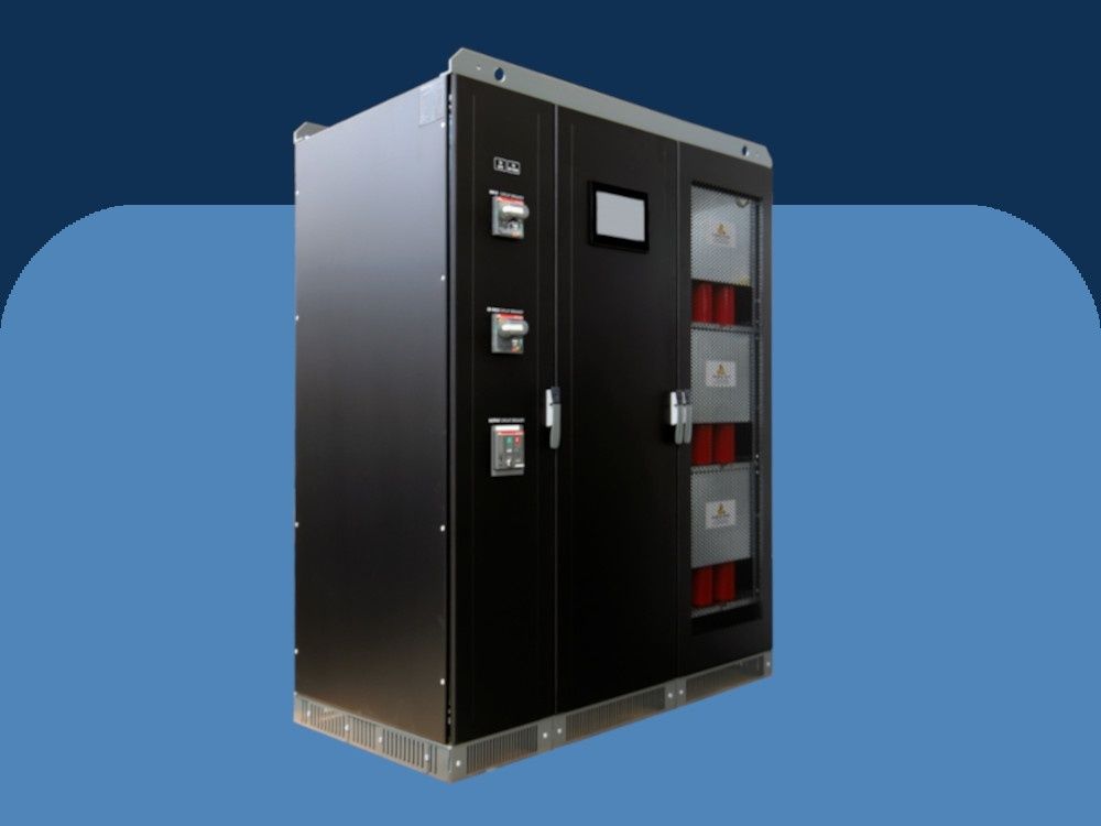
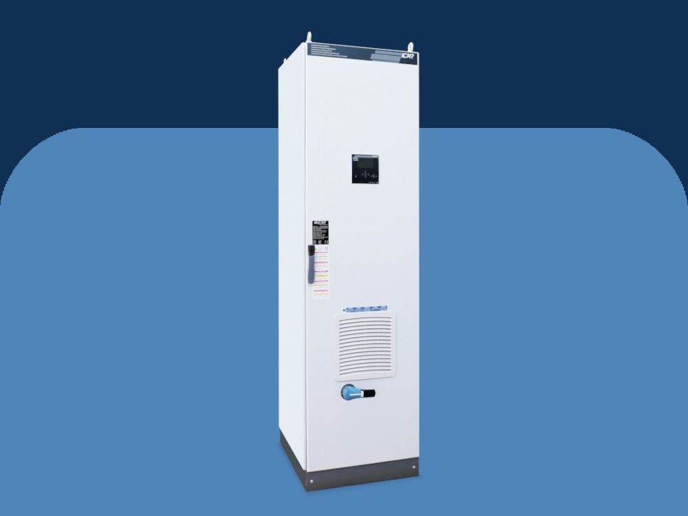
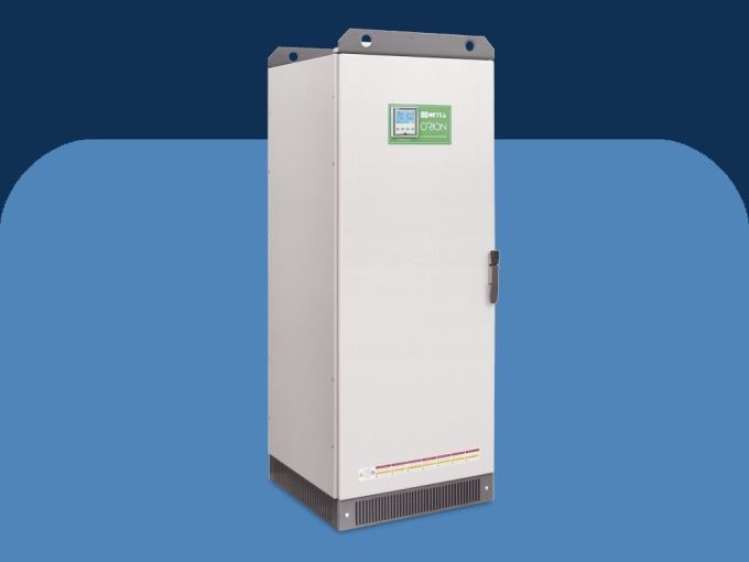
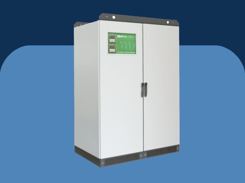
Orion - 3ph 2-135kVA electro-mechanical digitally controlled
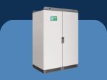
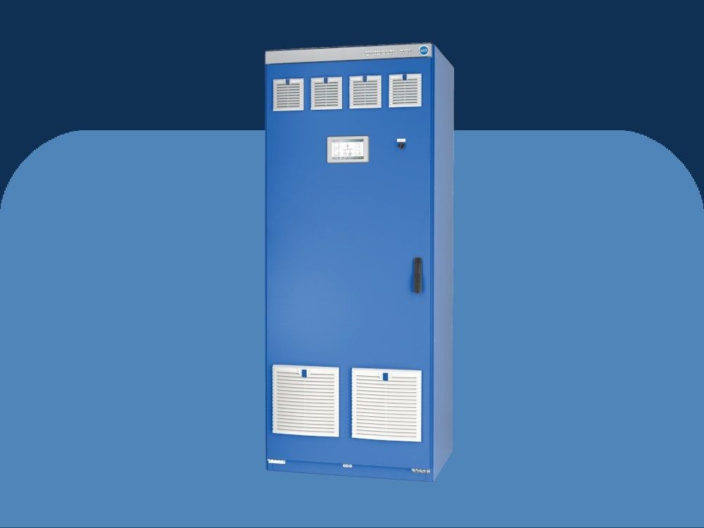
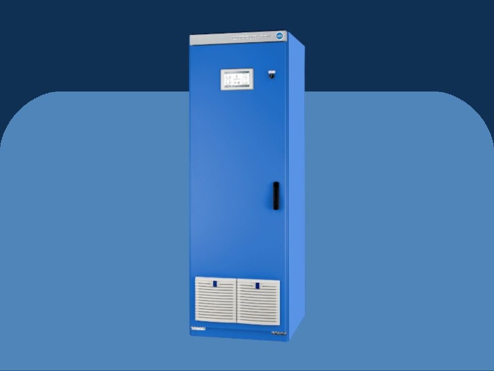
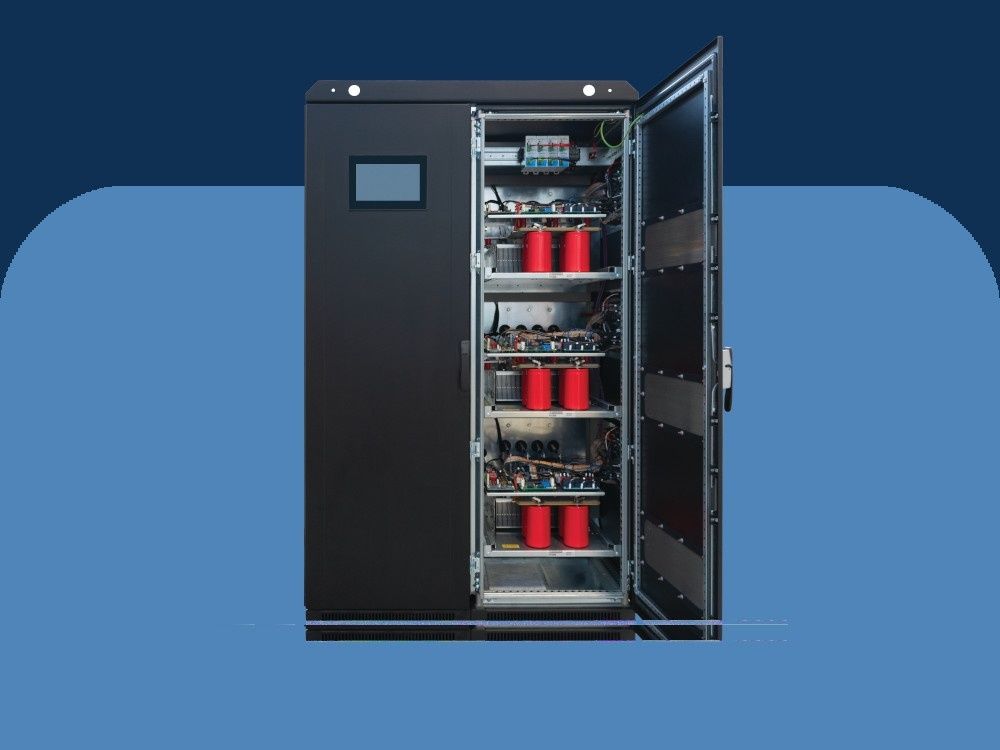
Orion is a three phase electro-mechanical stabilizer. The electromechanical stabilizers are digitally controlled and are made essentially of buck-boost transformer, voltage regulator and electronic control. By means of the digitally controlled system, the stabilizer is able to compensate for a widely fluctuating incoming voltage stabilizing it within a ±0.5% accuracy range in relation to the rated value. Based on a microprocessor sampling the output voltage at high frequency, the control system operates the voltage regulator motors in order to guarantee the voltage stability. The electromechanical stabilizers are often used in industrial installations, or installations of big nominal power, where the most important criteria are endurance in very high or very low voltages and a high degree of stabilization.
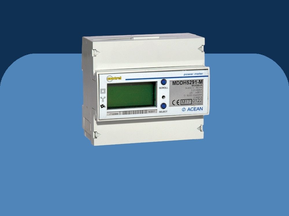
Orion stabilizers are available for different ranges of input voltage fluctuation. Standard models offer a double input connection so that with the same unit two different input variations (±15%/±20% or ±25%/±30%) can be dealt with. The output voltage regulation is performed independently on each phase (stabilization of each phase-to-neutral voltage). Orion stabilizers are used with three-phase loads and single-phase loads with 100% current imbalance across the phases and asymmetrical mains voltage. For the correct operation, Orion voltage stabilizers require the neutral wire presence. Operation without neutral wire connection is achievable by adding a device able to generate it (D/Yn isolating transformer or neutral point reactor). An automatic circuit breaker is mounted on the regulation circuit to protect against overload and short circuit on the voltage regulator, whilst the auxiliary circuit is protected by fuses. The instrumentation consists of a multi-task digital line analyzer. Such instrument is able to provide with information regarding the voltage stabilizer output parameters, such as phase and linked voltage, current, power factor, active power, apparent power, reactive power, etc. The alarms (min/max output voltage, gearmotor lock, internal overheating, regulator overload) are recognizable by means of LEDs on the control card. Voltage control and stabilization, performed on the true RMS value, are managed by the digital microprocessor. Each phase of every stabilizer belonging to this range is controlled by the same control board used on Vega and Antares models, thus simplifying maintenance operations and spare parts storage. Up to 45kVA, the stabilizers are equipped with wheels for easy handling.
- Voltage stabilization - Independent phase control
- Selectable output voltage (dip-switch) - 220-230-240V (L-N) / 380-400-415V (L-L)
- Output voltage accuracy: ±0,5%
- Frequency: 50Hz ±5% or 60Hz ±5%
- Admitted load variation - Up to 100%
- Admitted load imbalance - 100%
- Cooling
- Up to 45kVA ±15% natural ventilation
- From 60kVA ±15% (aided with fans) - Ambient temperature: -25/+45◦C
- Storage temperature: -25/+60◦C
- Max relative humidity <95% (non condensing)
- Admitted overload - 200% 2min.
- Harmonic distortion - None introduced
- Color - RAL 7035
- Protection degree IP 21
- Instrumentation Output digital mustimeter
- Installation Indoor
- Overvoltage protection Output class II surge arrestors
*Output voltage can be adjusted by choosing one of the indicated values.
Such choice sets the new nominal value as a reference for all the stabilizer parameters.
Buck/boost transformer
Often referred to as ‘booster’ transformer, it is a standard dry-type transformer with the secondary winding connected in series to the mains and the primary winding supplied by the voltage regulator.
Voltage regulator
Basically, it is an autotransformer with continuously variable transformer ratio. The voltage intake varies depending on the position of the rolling contacts; therefore the voltage supplied to the booster transformer primary winding also varies. Being the voltage across the regulator contacts (and consequently that on the secondary winding of the booster transformer) either in phase or in opposition to the supply voltage, it is then added or subtracted to the supply voltage, thus compensating its variations.
Auxiliary circuit with microprocessor
The DSP (Digital Signal Processor) microprocessor-based control circuit (specifically designed for drives with totally digitalised signal) compares the output voltage value to the reference one sampling it 2000 times per second. When an anomaly is detected, the control drives the voltage regulator gearmotor. By doing so, the regulator rollers change their position thus varying the voltage drawn and supplied to the buck/boost transformer primary winding. The input voltage variation is therefore automatically compensated. The control system and the construction methods of the machine ensure that the output accuracy is ± 0.5%.
- Interrupting devices
- Load protection against over/undervoltage
- Manual by-pass line
- Input isolating transformer
- SPD surge arrestor
- EMI/RFI filters
- Neutral point reactor
- Up to IP55 protection degree for indoor and outdoor installation
Combinations or one or more of the accessories listed in the following might result in an increase of the stabilizer overall dimensions and weight.

-b3ff238d.jpeg)
